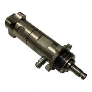
Repacking Titan 805-236A Fluid section assembly for Titan 840 and 740
Begin by removing the foot valve assembly and the lower housing. By following these procedures:
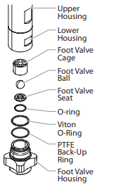
- Loosen and remove the foot valve housing from the lower housing.
- Clean out any debris in the foot valve housing and examine the housing and the foot valve seat. If the seat is damaged, reverse or replace the seat.
- Using two wrenches, hold the upper housing at the wrench flats with one wrench and loosen the lower housing with the other. Remove the lower housing.
- Using a 3/8” wrench, loosen and remove the outlet valve retainer from the piston rod.
Please note that the outlet valve does not require disassembly from the piston rod during this procedure.
Rotate the fluid section counterclockwise to detach it from the gearbox housing.
Secure the upper housing upright in a vise, taking care not to over-tighten to prevent damage.
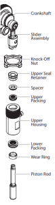
Utilizing a wrench, remove the upper seal retainer.
Slide the piston rod forward until the piston is out of the T-slot on the slider assembly.
Extract the Titan 805-437A Piston rod through the bottom of the upper housing.
Inspect the piston rod for wear and replace if necessary.
Remove the upper and lower packings from the upper housing, being careful not to damage the upper housing during the process.
Reassembly of the Parts
Clean the upper housing and inspect it for damage, replacing if needed.
Unwrap the upper packing and preform tool, using scissors to cut the plastic wrap (avoid using a utility knife to prevent damage to O-rings).
Slide the upper packing off the sizing/insertion tool towards the tip and install it into the top of the upper housing with the raised lip on the packing facing down.
Insert the spacer on top of the upper packing.
Thread the upper seal retainer into the upper housing and torque it to 25-30 ft. lbs.
Pre-form the lower packing using the lower packing sizing tool included in the repacking kit.
Install the lower packing with the side containing the O-ring closest to the face of the packing facing up.
Partially insert the lower packing into the bottom of the upper housing so that the O-ring side faces up.
Use the lower packing insertion tool to push the lower packing into position.
Place the piston insertion tool over the top of the piston rod.
Insert the piston rod into the bottom of the upper housing, through the lower packing, upper packing, and out through the upper seal retainer.
Ensure the raised lip on the bottom of the lower packing is fully outside the packing around the piston rod after insertion.
Remove the piston insertion tool from the top of the piston rod.
Slide the top of the piston rod into the T-slot on the slider assembly.
Turn the knock-off nut counterclockwise until it is flush against the upper housing.
Lubricate the threads on the upper housing with anti-seize compound, remove the upper housing from the vise, and thread it into the gearbox housing clockwise.
Continue turning the upper housing clockwise until the knock-off nut is flush against the gearbox housing.
If the nipple on the upper housing does not face the back of the unit, turn the upper housing counterclockwise until it does, avoiding more than one full turn.
Once the nipple is in position, turn the knock-off nut clockwise until it contacts the gearbox housing.
Tap the knock-off nut with a soft hammer to tighten it against the gearbox housing.
Ensure the Viton O-ring and PTFE back-up ring are lubricated and in place, then thread the lower housing into the upper housing. Use two wrenches to hold the upper housing at the wrench flats and tighten the lower housing.
Attach the high-pressure hose to the nipple on the back of the housing and tighten it with a wrench, avoiding kinking the hose.
For low rider units, ensure the hose does not touch the cart frame. If it does, reposition the nipple by turning the upper housing until the hose is clear of the frame, and the nipple is within 45º of the back of the unit.
Ensure the Viton O-ring and PTFE back-up ring are lubricated and in place, reassemble the foot valve assembly, and thread it into the lower housing securely.
Thread the siphon tube/siphon set into the foot valve and tighten it securely. Remember to wrap the threads on the down tube/siphon tube adapter with PTFE tape before assembly.
Replace the return hose into the clamp on the siphon tube.
Place the front cover on the gearbox housing and secure it in position using the four front cover screws.
Turn on the sprayer by following the procedure in the appropriate procedure and check for leaks.
Please note that a repacking kit with part number Titan 805-1010 Pump Repair Kit is available for this process.